CoroMill® QD
High-security groove milling and parting off
Instructions
Quick and easy insert changes save time. The quick-release key ensures the same clamping force over prolonged use thanks to no wear on the insert seat.Easy handling with quick-release key
Separate key available as an accessory for applications where the standard key cannot be used due to limited space, e.g. in gang milling.

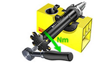
Use the torque tool for correct mounting.Torque tool
Driving collars for extra stability minimize vibration and ensure excellent quality grooves when using cutters with a high diameter-width ratio.Driving collar mounting
Smaller driving collars can be used together with face mill adapters in large machining centers as a cost-efficient solution.
Dampened Silent Tools™ adapters minimize vibration and provide stability when machining with long overhangs.Silent Tools™
Application tips
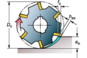
Maximum chip thickness
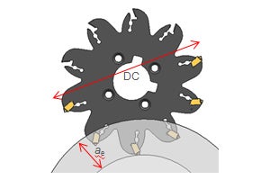
For parting and grooving milling applications, the most important factor to keep in mind is the maximum chip thickness (hex). Calculating cutting parameters according to the right hex value will ensure good cutting action with better surface quality and tool life.

Parting off
Parting off is often one of the last operations before the completion of the component, security is therefore of major importance. If the tool breaks during the parting, it generally scraps the component, but it may also lead to a longer machine stoppage.
Cutting data
Metric
| Geometry | Grade | vc m/min | |||||
| Diameter <160 mm | |||||||
| ISO P | ISO M | ISO K | ISO N | ISO S | ISO H | ||
| PL | 1030 | 220 (270–180) | 220 (290–180) | ||||
| 4340 | 220 (270–180) | ||||||
| PM | 1030 | 220 (270–180) | |||||
| 1130 | 220 (270–180) | | | | | | |
| 4340 | 220 (270–180) | ||||||
| PH | 1130 | 220 (270–180) | | | | | |
| 4340 | 220 (270–180) | | | | | | |
| ML | 1040 | 180 (200–160) | 180 (225–160) | 30 (60–20) | |||
| 2040 | 230 (275–210) | ||||||
| MM | 1040 | 180 (200–160) | 180 (225–160) | 30 (60–20) | |||
| 2040 | 230 (275–210) | ||||||
| KL | 1020 | 190 (205–165) | |||||
| 3330 | 220 (250–190) | ||||||
| KM | 1020 | | | 190 (205–165) | | | |
| 3330 | | | 220 (250–190) | | | | |
| SL | 1030 | 220 (270–180) | 35 (80–30) | 30 (45–25) | |||
| S30T | 240 (310–220) | 40 (80–30) | 40 (45–30) | ||||
| SM | 1030 | 220 (270–180) | 35 (80–30) | 30 (45–25) | |||
| S30T | 240 (310–220) | 40 (80–30) | 40 (45–30) | ||||
| S40T | 210 (275–190) | 35 (80–30) | |||||
| NL | H13A | | 985 (1030–945) | ||||
| Geometry | Grade | vc m/min | |||
| Diameter >160 mm | |||||
| ISO P | ISO M | ISO K | ISO N | ||
| PL | 1030 | 180 (270–180) | 180 (290–180) | ||
| | 4340 | 180 (270–180) | |||
| PM | 1030 | 180 (270–180) | |||
| | 1130 | 180 (270–180) | | | |
| | 4340 | 180 (270–180) | |||
| PH | 1130 | 180 (270–180) | | | |
| | 4340 | 180 (270–180) | | | |
| ML | 1040 | 160 (200–160) | 160 (225–160) | ||
| | 2040 | 210 (275–210) | |||
| MM | 1040 | 160 (200–160) | 160 (225–160) | ||
| | 2040 | 210 (275–210) | |||
| KL | 1020 | 160 (205–165) | |||
| | 3330 | 190 (250–190) | |||
| KM | 1020 | | | 160 (205–165) | |
| | 3330 | | | 190 (250–190) | |
| SL | 1030 | 200 (270–180) | |||
| | S30T | 210 (310–220) | |||
| SM | 1030 | 200 (270–180) | |||
| | S30T | 210 (310–220) | |||
| | S40T | 190 (275–190) | |||
| NL | H13A | | 985 (1030–945) | ||
Note:
For Inconel, recommended vc = 25 (45–20) m/min
For titanium, recommended vc = 35 (80–30) m/min
Inch
| Geometry | Grade | vc ft/min | |||||
| Diameter <6 inches | |||||||
| ISO P | ISO M | ISO K | ISO N | ISO S | ISO H | ||
| PL | 1030 | 720 (880–590) | 220 (290–180) | ||||
| | 4340 | 720 (880–590) | |||||
| PM | 1030 | 720 (880–590) | |||||
| | | | | | | | |
| | 4340 | 720 (880–590) | |||||
| PH | 1130 | 720 (880–590) | | | | | |
| | 4340 | 720 (880–590) | | | | | |
| ML | 1040 | 590 (655–525) | 590 (655–525) | 95 (195–65) | |||
| | 2040 | 590 (655–525) | |||||
| MM | 1040 | 590 (655–525) | 590 (655–525) | 95 (195–65) | |||
| | 2040 | 755 (900–685) | |||||
| KL | 1020 | 620 (670–540) | |||||
| | 3330 | 720 (885–590) | |||||
| KM | | | | 620 (670–540) | | | |
| | | | | 720 (820–620) | | | |
| SL | 1030 | 720 (885–590) | 115 (260–65) | 95 (145–80) | |||
| | S30T | 785 (1015–720) | 130 (260–65) | 130 (145–95) | |||
| SM | 1030 | 720 (885–590) | 115 (260–65) | 95 (145–80) | |||
| | S30T | 785 (1015–720) | 130 (260–65) | 130 (145–95) | |||
| | S40T | 685 (900–620) | 115 (260–65) | ||||
| NL | H13A | | 3230 (3380–3100) | ||||
| Geometry | Grade | vc ft/min | |||
| Diameter >6 inches | |||||
| ISO P | ISO M | ISO K | ISO N | ||
| PL | 1030 | 590 (885–590) | 590 (950–590) | ||
| | 4340 | 590 (885–590) | |||
| PM | 1030 | 590 (885–590) | |||
| | 1130 | 590 (885–590) | | | |
| | 4340 | 590 (885–590) | |||
| PH | 1130 | 590 (885–590) | | | |
| | 4340 | 590 (885–590) | | | |
| ML | 1040 | 525 (655–525) | 525 (735–525) | ||
| | 2040 | 685 (900–685) | |||
| MM | 1040 | 525 (655–525) | 525 (735–525) | ||
| | 2040 | 685 (900–685) | |||
| KL | 1020 | 520 (670–540) | |||
| | 3330 | 620 (820–620) | |||
| KM | | | | 520 (670–540) | |
| | | | | 620 (820–620) | |
| SL | 1030 | 655 (885–590) | |||
| | S30T | 685 (1015–720) | |||
| SM | 1030 | 655 (885–590) | |||
| | S30T | 685 (1015–720 | |||
| | S40T | 620 (900–620) | |||
| NL | H13A | | 3230 (3380–3100) | ||
Note:
For Inconel, recommended vc = 80 (145–65) ft/min
For titanium, recommended vc = 115 (260–100) ft/min
Recommendations
Torque
| Coupling size | Torque, Nm (ft/lbs) |
| X10 | 6.4 (4.7) |
| X22/Y25 | 3.9 (2.9) |
| X32/Y31 | 6.4 (4.7) |
| X40* | 70 (51.6) |
* Note: Not countersunk screws.
Coolant pressure
Higher internal coolant pressure improves chip evacuation.
| Seat size | Maximum coolant pressure, bar (PSI) |
| E, F | 50 (725) |
| G, H, J, K | 70 (1,015) |
Maximum chip thickness – hex
Metric
| Geometry |
Grade |
hex |
||||||
| ISO P | ISO M | ISO K | ISO N | ISO S | ISO H | |||
| PL |
1030 | 0.05 (0.02–0.08) | 0.05 (0.02–0.08) | |||||
| 4340 | 0.05 (0.02–0.08) | |||||||
|
PM |
1030 | 0.11 (0.07–0.15) | | | | | |
Seat size E, F, G, H, J |
| 1130 | 0.11 (0.07–0.15) | | | | | | ||
| 4340 | 0.11 (0.07–0.15) | | | | | | ||
|
PM |
1030 | 0.10 (0.07–0.10) | | | | | |
Seat size K |
| 1130 | 0.10 (0.07–0.10) | | | | | | ||
| 4340 | 0.10 (0.07–0.10) | | | | | | ||
|
PH |
1130 | 0.11 (0.04–0.13) | | | | | |
Seat size E, F, G, H, J |
| 4340 | 0.11 (0.04–0.13) | | | | | | ||
|
PH |
1130 | 0.10 (0.04–0.10) | | | | | |
Seat size K |
| 4340 | 0.10 (0.04–0.10) | | | | | | ||
|
ML |
1040 | 0.04 (0.01–0.07) | 0.04 (0.01–0.07) | | | 0.11 (0.07–0.15) | | |
| 2040 | | 0.04 (0.01–0.07) | | | | | ||
|
MM |
1040 | 0.08 (0.04–0.12) | 0.08 (0.04–0.12) | | | 0.11 (0.07–0.15) | | |
| 2040 | | 0.08 (0.04–0.12) | | | | | ||
|
KL |
1020 | | | 0.11 (0.02–0.15) | | | | |
| 3330 | | | 0.11 (0.02–0.15) | | | | ||
|
KM |
1020 | | | 0.11 (0.02–0.15) | | | | |
| 3330 | | | 0.11 (0.02–0.15) | | | | ||
|
SL |
1030 | | 0.04 (0.01–0.07) | | | 0.04 (0.01–0.07) | 0.04 (0.01–0.07) | |
| S30T | | 0.04 (0.01–0.07) | | | 0.04 (0.01–0.07) | 0.04 (0.01–0.07) | ||
|
SM |
1030 | | 0.08 (0.04–0.12) | | | 0.08 (0.04–0.12) | 0.08 (0.04–0.12) | |
| S30T | | 0.08 (0.04–0.12) | | | 0.08 (0.04–0.12) | 0.08 (0.04–0.12) | ||
| S40T | | 0.08 (0.04–0.12) | | | 0.08 (0.04–0.12) | | ||
| NL | H13A | | | | 0.13 (0.01–0.25) | | ||
Inch
| Geometry |
Grade |
hex |
||||||
| ISO P | ISO M | ISO K | ISO N | ISO S | ISO H | | ||
| PL |
1030 | 0.002 (0.001–0.003) | 0.002 (0.001–0.003) | |||||
| 4340 | 0.002 (0.001–0.003) | |||||||
|
PM |
1030 | 0.004 (0.003–0.003) | | | | | |
Seat size E, F, G, H, J |
| 1130 | 0.004 (0.003–0.003) | | | | | | ||
| 4340 | 0.004 (0.003–0.003) | | | | | | ||
|
PM |
1030 | 0.004 (0.003–0.003) | | | | | |
Seat size K |
| 1130 | 0.004 (0.003–0.003) | | | | | | ||
| 4340 | 0.004 (0.003–0.003) | | | | | | ||
|
PH |
1130 | 0.004 (0.002–0.003) | | | | | |
Seat size E, F, G, H, J |
| 4340 | 0.004 (0.002–0.003) | | | | | | ||
|
PH |
1130 | 0.004 (0.002–0.003) | | | | | |
Seat size K |
| 4340 | 0.004 (0.002–0.003) | | | | | | ||
|
ML |
1040 | 0.002 (0.001–0.003) | 0.002 (0.001–0.003) | | | 0.002 (0.001–0.003) | | |
| 2040 | | 0.002 (0.001–0.003) | | | | | ||
|
MM |
1040 | 0.003 (0.002–0.005) | 0.003 (0.002–0.005) | | | 0.003 (0.002–0.005) | | |
| 2040 | | 0.002 (0.002–0.005) | | | | | ||
|
KL |
1020 | | | 0.004 (0.001–0.006) | | | | |
| 3330 | | | 0.004 (0.001–0.006) | | | | ||
|
KM |
1020 | | | 0.004 (0.001–0.006) | | | | |
| 3330 | | | 0.004 (0.001–0.006) | | | | ||
|
SL |
1030 | | 0.002 (0.001–0.003) | | | 0.002 (0.001–0.003) | 0.002 (0.001–0.003) | |
| S30T | | 0.002 (0.001–0.003) | | | 0.002 (0.001–0.003) | 0.002 (0.001–0.003) | ||
|
SM |
1030 | | 0.003 (0.002–0.005) | | | 0.003 (0.002–0.005) | 0.003 (0.002–0.005) | |
| S30T | | 0.003 (0.002–0.005) | | | 0.003 (0.002–0.005) | 0.003 (0.002–0.005) | ||
| S40T | | 0.003 (0.002–0.005) | | | 0.003 (0.002–0.005) | | ||
| NL | H13A | | | | 0.005 (0.001–0.01) | | ||
Note: Maximum hex for seat size K is limited because of cutter body.
Recommendation for diameter 63 mm (2.5 inch) cutters
-
PL is the First choice geometry in ISO P applications
-
Use maximum 70% of the recommended hex value when using the PM geometry
-
PH geometry is not recommended
Join us. Stay updated.
Sign up for our newsletter today


